The flyback converter is a DC to DC converter with a galvanic isolation between the input and the output(s). The flyback converter includes the isolation transformer into its design on the high frequency DC switching side, avoiding the bulky and costly AC50hz transformer that would otherwise be required to achieve isolation.
Including an isolation transformer also allows for multiple output voltages using the same core . The regulation circuitry can also take advantage of the turns ratio inherent in the transformer, allowing for a suitable selection for the range of D despite any conversion requirements.
However the inclusion of a transformer increases the cost, size and complexity of the power supply design.
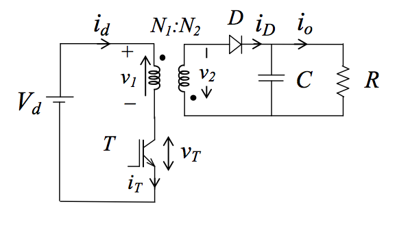
Circuit Diagram[]
Analysis[]
Unlike other DC converters an additional relationship must be known to successfully complete the analysis, Faradays Induction Law,
. Which states the voltage across the windings of a transformer is equal to the changing magnetic flux through 1 turn times the number of turns on that side. This relationship will take the place of the inductor energy equations used in previous DC-DC analysis.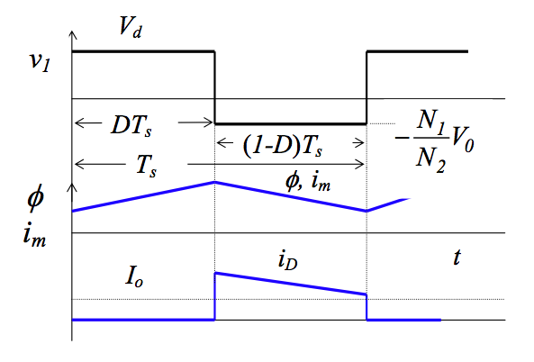

Ton[]
Ton
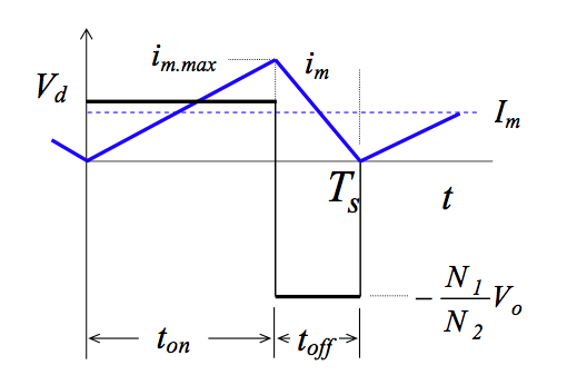
During Ton current flows through the inductor Lm charging it up, but no current flows through the diode and the capacitor supplies the output current. Voltage across the inductor is the supply voltage.
Hence

Max flux = start flux + flux pumped in during Ton, which is the area under the curve


We now have an expression for the max magnetic flux.
Toff[]
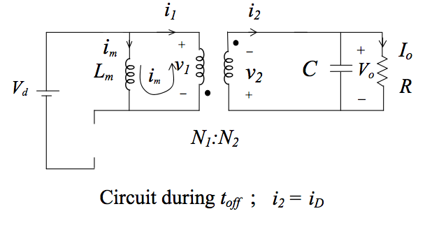
Toff
During Toff the supply is switched out, and the inductor and the magnetic flux in the primary side are trying to get rid of there energy as they cannot continue to conduct. They reverse the voltage to get rid of it and start to supply energy to the capacitor and load through the diode.

We want to find the final value for magnetic flux for Toff like we did for Ton.
Start flux plus change in energy.

now

If at


which gives us the relationship betwen the input and output voltage for continous conduction mode.
Boundary between dis and cts Conduction[]

The inductor current must be discontinuous to ensure full demagnetisation of the transformer core.
Whether the current is continuous or discontinuous is dependent upon the load, so we want to find a relationship between the load and the inductor which will describe the boundary between cts and discts conduction.
Since we have an ideal converter we can use energy conservation as a start.
Nguyen Nhu Bao Viet
input power equals output power


Also supplied current is equal to inductor current during Ton


Using relationship between input and output voltages in cts mode

We now have an expression for the average inductor current in terms of the output and load.
Now we can assume that the average current plus/minus half the change in inductor current with give us the maximum and minimum values of im respectively.
We are only concerned with the minimum value and when it equals zero, as that is the boundary between cts and dis conduction.

We have an expression for Im but the change comes from the relationship between voltage and current in an inductor
We will use the change in inductor current during the Ton part of the cycle, it doesn't matter which cycle if we are assuming energy is idealy conserved.

So it can be found

Flyback Under Dis Conduction[]
Again we want to find a relationship between input voltage and output, but this time under discontinous conduction.

From previous


Total change equal to max as we start from zero

so


Output Voltage Ripple[]
Output voltage ripple for cts mode can be found by analysing the change in the capacitor voltage.


The voltage ripple for discontinuos conduction will be greater as the capacitor is the source of current for longer.
Practical Considerations and Ratings[]
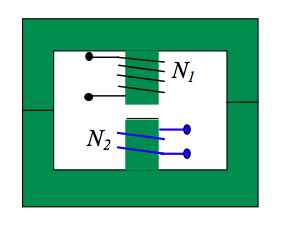
Transformer Considerations[]
The choice of transformer for the flyback converter has a number of special requirements
- The flyback converter unidirectionally excites the core, because of this special precaution must be taken as not to saturate the core. Some effective strategies include air gaps in the core(iincreasing flux leakage) or special snubber circuits which are used to 'reset' the flux each switching cycle. Using a combination of both can deliever efficient transformers and lower ratings on snubber circuit

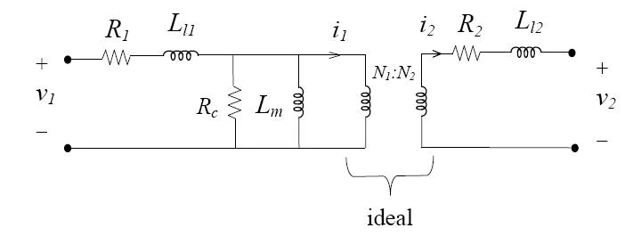
- The inductances and must be as small as possible to reduce power loss in the switching circuitry.

- should be small. This is written in the notes, I assume because in cts conduction mode the output voltage is independent of L and during the discts it is inversely proportional. Also because the core of the transformer is the energy storage device in the flyback, until other dc-dc converters and as such a large value of L is not needed to store the energy required to power the circuit.
- It should also be noted that discontinuous mode utilises the transformer more effectively, and requires smaller snubber circuitry.


Switch Ratings[]
Max voltage across the switch occurs during Toff

From input voltage to output voltage relationship found above

Two Switch Flyback Converter[]
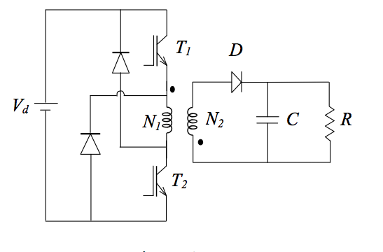
- Transistors T1 and T2 are turned on and off simultaneously.
- Energy trapped in the leakage inductances now has a regenerative path to flow through.
- Trapped energies in these inductances return to the DC source. Snubber requirement is thus even smaller.
- The two transistors may have half the voltage rating of the single-transistor flyback converter.