Please note that these are all examples and not necessarily the best design choices.
Conceptual Design[]
Functional Description[]
This should give an overview of what this block is trying to achieve. e.g:
The low-pass filter eliminates high frequency noise by creating a break point at frequencies above those that humans can hear. Minimum ripple in the pass-band is desired to avoid distorting the audio signal.
Block Diagram and Description[]
This can include a block diagram, a transfer function/pole zero diagram and a description of any diagrams. e.g:
The low-pass filter is a first order RC circuit with the following transfer function:

Design Parameters[]
This should include as much information as possible. These parameters will be a combination of both restrictions placed upon the designer by other parts of the circuit, and properties of your block for the benefit of those designing blocks adjacent to yours.
Input Parameters[]
| Input Impedance | 100k |
| Maximum Input Voltage | 1V |
Output Parameters[]
| Output Impedance | 10k |
| Maximum Output Voltage | 10 V |
| Maximum Output Current | 1TA |
Transfer Parameters[]
| 3dB frequency | 20kHz |
| Pass-Band Ripple | <1dB |
Design Implementation[]
The details of on-going design should be maintained here.
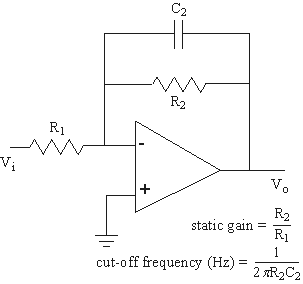
Circuit Diagram and Description[]
The diagram below shows the circuit topology which meets the requirements of the transfer function above.
Performance Testing[]
In this section, the completed circuit should be tested to see how well it conforms to the given design parameters. Any other pertinent information should be included also.
Input Parameters[]
| Input Impedance | 100k |
| Maximum Input Voltage | 1V |
Output Parameters[]
| Output Impedance | 10k |
| Maximum Output Voltage | 10 V |
| Maximum Output Current | 1TA |
Transfer Parameters[]
| 3dB frequency | 20kHz |
| Pass-Band Ripple | <1dB |