Waveguide Modes[]
Wave Equations[]
From Maxwell's equations, the field equation of a plane wave propagating along a waveguide can be derived, in terms of the spatial dimensions , and , and the temporal dimension , as


where is the 2-dimensional cross-section of the distribution of the electromagnetic field, is the propagation constant, and is the angular frequency of the wave excitation in units of radians (with being the frequency in hertz). Technical names exist for each term in the equation:


- is called the transverse term
- is known as the phase term
- is the harmonic term


Note that the wave propagation is in the -direction, and since the cross-sectional field pattern is normally assumed constant, it is therefore customary to express the wave equation without and dependence as

where only the phase changes along the waveguide axis (-direction). By comparing this with the general equation for wave propagation , where is the velocity of the propagation, it is simple to define the propagation velocity of the wave as


Recalling that the speed of light in a specific material (i.e. the waveguide) of refractive index is given by


where m/s is the speed of light in free space, and is the free space wavenumber (with being the wavelength), we see that , or put another way, the effective refractive index of the waveguide is


which always satisfies < < , where and are the refractive indices of the waveguide cladding and core, respectively.


Degree of Guidance[]
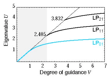
Figure 1: U(V) curves for a step index fibre.
The degree of guidance of a waveguide gives an indication on the total number of individual modes that the waveguide can support. It is given by

where is the characteristic dimension of the waveguide (e.g. it is the half-thickness of a slab/square waveguide, the radius for a circular waveguide or optical fibre, and the e-folding distance of a graded-index waveguide), and is known as the index contrast. In practical systems, we are usually interested in number of supportable modes for a given waveguide, at different wavelengths (frequencies). To determine this, the degree of guidance is first calculated for a particular wavelength. The result is then compared with the eigenvalue U(V) graph for the particular dimensions and index contrast of the waveguide. An example is shown in Figure 1 for a step index fibre. For instance, if the degree of guidance is calculated to be 2.4, then from looking at the graph, we see that only one mode (i.e. the Failed to parse (unknown function "\sf"): {\displaystyle \sf LP_{01}} or fundamental mode) is supported, since no other modes have an intersection point before V = 2.4. On the other hand, if the degree of guidance is calculated as say, 3.5, then two modes (i.e. the Failed to parse (unknown function "\sf"): {\displaystyle \sf LP_{01}} and Failed to parse (unknown function "\sf"): {\displaystyle \sf LP_{11}} modes) will be supported.


These results are important in telecommunication systems that employ optical fibre links. Having more than one supportable mode in a waveguide (optical fibre) means that inter-mode interference will occur, hence degrading communication performance. Telecommunications engineers thus seek to reduce the degree of guidance to achieve single-moded fibres. This can be done by increasing the wavelength of communication. However, in bandlimited systems, this may not be feasible, and so the physical charateristics of the fibre (i.e. size or index contrast) may be varied. Of course, waveguide modes are important in contexts other than telecommunications.
See Also[]
The page on propagation coming to an elsoc.wikia page near you!