Purpose[]
The purpose of this project is to design, test and fabricate a small audio amplifier capable of amplifying a guitar/keyboard signal to a level able to be heard easily by human ears. The amplifier should have as little noise and distortion as possible. This design will have utility in future projects as signal processing electronics can act as an input to the amplifier and hence the signals can be coverted to sound and heard by designers.
Design Specification[]
This section should eventually have a well defined design specification. These values should be debated among members and decided upon based upon the best alternative and will change with trial and error. Feel free to add any design parameters you think are appropriate and we can debate their values via the discussion page.
| Load Power (RMS) | 2 W |
| Max Operating Voltage | 30V |
| Min Operating Voltage | 20V |
| Total Harmonic Distortion | <5% |
| low cut-off frequency | 10Hz |
| high cut-off frequency | 22kHz |
| Input Impedance | >60k |
| Voltage Gain | 200 |
| Output Voltage Swing | +15-15 |
| Power Supply Rejection Ratio (PSRR) @ 1kHz | 90dB |
| Power Supply Rejection Ratio (PSRR) @ 20 kHz | 50dB |
| Short Circuit Current | 11 A |
| a | 1 |
| b | 1 |
| c | 1 |
| d | 1 |
Conceptual Design[]
A suggested conceptual design is given in the block diagram. Please offer thoughts/improvements via the discussion page. Also think about which block you would like to work on.
The guitar input block involves testing a guitar input and recording electrical parameters such as maximum input amplitude and output impedance. The output impedance of the guitar is important because if the input resistance of our amplifier is about the same or smaller than the output impedance of the guitar, most of the signal will be dropped inside the guitar and hence we've decrease our signal to noise ratio .
The voltage amplifier boosts the tiny input voltage to a level able to be amplified by the power/current amplifier, whilst cutting high frequencies (beyond human hearing) out to reduce suscetibilty to instability (as active filters can provide gain as well as shaping). Alternatively it might be better to have a passive low pass filter as it may introduce less noise or maybe none at all.
The current amplifier drives the current to a level suitable to drive the loudspeaker. The power supply will initially be the lab power supplies although we may eventually design one or buy an off-the-shelf package. In the mean time, we will need to measure the 50Hz ripple in the power supply to determine the magnitude of its contribution to distortion. 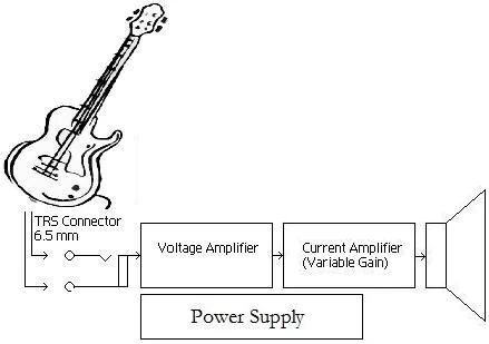
Example[]
Follow this link for a good example of a 15-watt amplifier, designed by a guy called Sergio Garcia. I have included a quick description of the topology.
Design Implementation[]
When the conceptual design is decided upon, I will, or members can, create pages for their functional block. Record all design ideas, parameters and measured values here. Please follow the naming convention when making a page.
- Audio:Simple Amplifier:Preamplifier (voltage)
- Audio:Simple Amplifier:Power Amplifier (current)
- Audio:Simple Amplifier:Power Supply
- Audio:Simple Amplifier:Speaker
The current PSPICE schematic for the amplifier can be found at the link below.
1) Paste the text into a new text document
2) Add a '*' at the very beggingin of the text (I had to omit the star from the wiki because the wiki sees it as a dot point)
3) Change the file extension from .txt to .sch and hopefully it will open with Schematics.
Performance Testing[]
This section is for the performance of the amplifier as a whole unit. Record individual block performance in the page allocated for that block, not here. Feel free to add any test parameters you think might be appropriate. An example is included:
| Maximum Output Power (RMS) | 1.97 W |
| Total Harmonic Distortion | |
| low cut-off frequency | |
| high cut-off frequency | |
| Input Impedance | |
| Voltage Gain | |
| Output Voltage Swing | |
| Power Supply Rejection Ratio (PSRR) @ 1kHz | |
| Power Supply Rejection Ratio (PSRR) @ 20 kHz | |
PCB Layout[]
When the circuit diagram has been completed and tested, the PCB layout should go here. Hopefully we will be able to get it fabricated..