Conceptual Design[]
Functional Description[]
The Pulse Generator should create a train of pulses 'n' pulses every 't' milliseconds, as shown in the timing diagram below.
![]()
Block Diagram[]
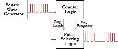
The square wave generator outputs a square wave which is counted by the counter logic. The counter logic counts to 'n' (the desired number of edges) and outputs "high" for the length of time it takes 'n' oscillations to complete. This is called the "ping length". The second function of the counter logic is to count the desired length of time between pings and output "high" at this interval. The pulse selecting logic then performs logical AND operations on these waveforms and the desired output is obtained.
Design Parameters[]
| Square Wave Period | 1 ms |
| Square Wave Duty Cycle | 50% |
| Period Between Pings | 1 s |
Design Implementation[]
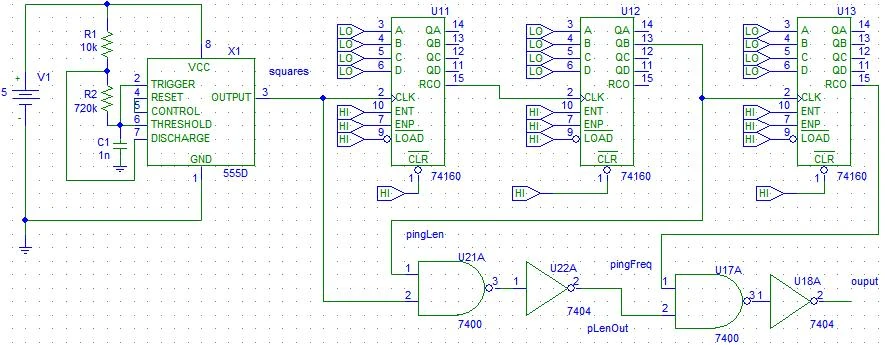
The 555 timer is set up to oscillate at a frequency of 1 kHz. The output is a square wave of duty cycle just below 50%. The square wave serves as the clock input on the first 4-bit counter. The reset signal is then cascaded to the next counter, with the second-least significant bit (QB) being cascaded to the subsequent counter. The square wave is ANDed with QB of the second counter, the output of which is 16 square wave pulses every time QB goes high. This modulates the number of pulses in each ping. To modulate the interval between pings, the third counters' RCO outputs high every 1 second. This signal is then ANDed with the 16 pulse signal to obtain 16 pulses every second.
Performance Testing[]
Parts List[]
ICs[]
1 x NE555P timer
3 x DM74LS161AN 4 bit counter
1 x SN74HC132N Quad NAND
Passive Components[]
1 x 1 nF greencap
1 x 10k Ohm
1 x 680k Ohm
1 x 39k Ohm
1 x 2.2k Ohm