Abstract
Introduction[]
Purpose and Background[]
The purpose of this project is to design and build a multi-purpose FX-pedal for guitar, keyboard and bass guitar. FX-pedals are electronic devices that affect the sound of an electric or electronic instrument or other audio source in real time [1].
FX-pedals are primarily used by musicians during live performances or recording to shape their sound to a desired tone colour. The shaping of the instruments tone colour can dramatically change the overall sound of a song and indeed in some cases can be a defining feature in a style of music.
For example: Heavy Metal almost invariably uses distortion on a guitar at some point during a song. Note the distorted/fuzzy sound of the guitar riff in the video below:
Another example: The use of Wah Wah in Funk. Note the wah-wah sound on the guitar in the video below:
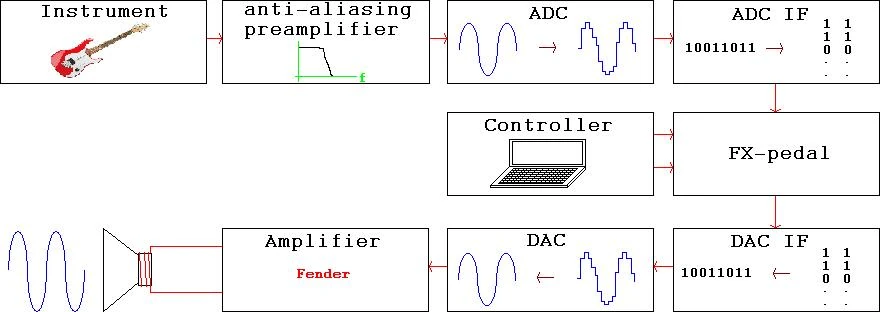
The FX-pedal is generally used by plugging an instrument into it and taking a lead out of it which goes to the amplifier. It can be controlled in a variety of ways such as via a foot switched pedal, using knobs and switches, via a PC GUI, etc.
Some FX commonly in use today are Distortion, Delay, Reverb and Wah Wah.
Abbreviations[]
ADC - analogue to digital converter DAC - digital to analogue converter
FX - Guitar Effects
GUI - Graphical User Interface
HDL - Hardware Description Language
PC - Personal Computer
VHDL - Very High Speed Hardware Description Language
Design[]
Conceptual Design[]
Input Signal Parameters[]
Description[]
The instrument can be modelled as a voltage source with a series resistance. Different instruments put out different voltage amplitudes. This can be tested in the lab and is an important design parameter to consider when designing the preamplifier.
Design[]
Anti-Aliasing Preamplifier[]
Description[]
The preamplifier serves two main roles:
- To amplify the signal to a level suitable for the input of the ADC. This requirement can be determined by reading the ADC data sheet.
- To filter the signal before sampling so that aliasing distortion is avoided. For more information, read wikipedia on the topics of sampling and aliasing. The sample rate is an important design parameter and would usually be around 44 kHz
Anti-Aliasing Filter Design[]
Amplifier Stage Design[]
ADC[]
Description[]
The ADC takes a sample of the input analogue waveform and translates it into serial binary data. Note that the ADC is already on the board, so we do not need to design one, just understand how the existing one works.
Design[]
DAC[]
Desciption[]
The DAC takes serial binary data and translates it into an analogue voltage. Note that the DAC is already on the board, so we do not need to design one, just understand how the existing one works.
Design[]
HDL Design[]
Top Levels[]
ADC Interface[]
Description[]
The ADC interface takes serial data from the ADC and puts it in a form usable by the FX-pedal. Note that this is internal to our design and hence this is the first block that will need HDL coding. Also note that plenty of ADC manufacturers provide sample code for ADC interfaces; these may be used as a starting point when designing our system.
Design[]
DAC Interface[]
Description[]
The DAC interface takes parallel data from the FX-pedal and puts it in the serial form needed by the DAC. Note that this is internal to our design and hence will need HDL coding. Also note that plenty of DAC manufacturers provide sample code for DAC interfaces; these may be used as a starting point when designing our system.
Design[]
FX-Pedal[]
Description[]
This is our actual design. At first, this block will be simply an HDL module connecting the signals coming in from the ADC IF directly to the DAC IF. Once the other blocks are complete and a signal succesfully travels from the instrument, through the FPGA, to the speaker, work on the FX-pedal can start. This can be any sort of processing imaginable; a clipper for distortion, a flanger, a low frequency oscillator, the sky's the limit.
Design[]
Controller[]
Description[]
This is the means used to control the functionality of the FX-pedal, i.e. to select which FX are used. In the spirit of keeping the intial design as simple as possible and adding complexity later, I propose making use of the on-board switches for this purpose. Later, a graphical user interface (GUI) may be designed
Design[]
Output Amplifier[]
Description[]
At the moment the amplifier is a small Fender bass amp, with speaker included. However, this block may need additional design to condition the output of the DAC for the input of the amplifier. For example, the output voltages of the DAC may overdrive the amplifier and hence this signal will need to be reduced and a protection circuit will need to be built
Design[]
Testbench Design[]
Overview[]
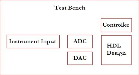
The testbench emulates the entire system, for the purpose of simulating and verifying a design. System components that are external to the HDL design need to be emulated in HDL. For example, the ADC behaves in a certain way in terms of inputs and outputs. It takes in an analogue input (represented by an integer) and outputs a serial binary stream representative of the sampled voltage. This can all be emulated using HDL, so that the entire system may be simulated
Note the abscence of the preamplifier, the output amplifier and the speaker. All of these items are not needed in simulation as the problems they solve exist only in the analogue world and are not needed to verify the HDL design. All remaining modules must have HDL code written for their test bench emulation.
ADC[]
DAC[]
Controller[]
Input Signal[]
Implementation[]
Tools and Methodologies[]
Input Signal[]
Analog Simulation[]
Matlab[]
Core Generator[]
HDL[]
The HDL chosen is Verilog. This is because Verilog is currently being taught at UNSW. The downside is that Verilog is shit compared to VHDL PeterOliver 14:11, April 22, 2010 (UTC)
Digital Simulation[]
Xilinx ISE Suite[]
Architecture[]
ADC[]
The ADC used is on the Spartan board and a description can be found in the users guide. The ADC is a Linear Tech LTC1407A-1 Dual A/D and its datasheet can be found at the following link:
http://cds.linear.com/docs/Datasheet/14071fb.pdf
DAC[]
The DAC used is on the Spartan board and a description can be found in the users guide. The DAC used is a Linear Tech LTC2624 Quad DAC and its data sheet can be found at the following link:
http://cds.linear.com/docs/Datasheet/2604fd.pdf
Digital Logic[]
The FPGA board used is the Spartan-3E Starter Kit. It's documentation can be found at the following link:
http://www.xilinx.com/support/documentation/spartan-3e_board_and_kit_documentation.htm
Note especially the User Guide
http://www.xilinx.com/support/documentation/boards_and_kits/ug230.pdf
Controller[]
For now the controller is simply implemented via the switches on the development board (See user guide for details). In future this may be controlled via a foot pedal or a GUI.
File Organisation[]
The files should be organised in a structured way on a USB drive. This drive should be backed up after each week onto another machine.
Digital Design Process Overview[]
Coregen[]
Simulation[]
Xilinx ISE[]
Controller[]
PCB Layout[]
Enclosure[]
Performance Testing[]
Experimental Setup and Implementation[]
Results[]
References and Links[]
References[]
[1] http://en.wikipedia.org/wiki/FX_Pedal